
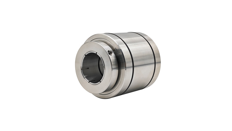
KVF Series
The ferrofluid adopts double-flange connection. When the drive shaft is inserted into the shaft sleeve, two O-rings inside the sleeve compress the drive shaft to form a static seal between them. The rotation of the drive shaft drives the shaft sleeve to rotate together, solving the vacuum sealing problem of the drive shaft. To prevent shaft slipping, the hose clamp at the tail of the shaft sleeve must lock the shaft. It is suitable for vacuum sealing at medium and low rotational speeds under ambient temperature.
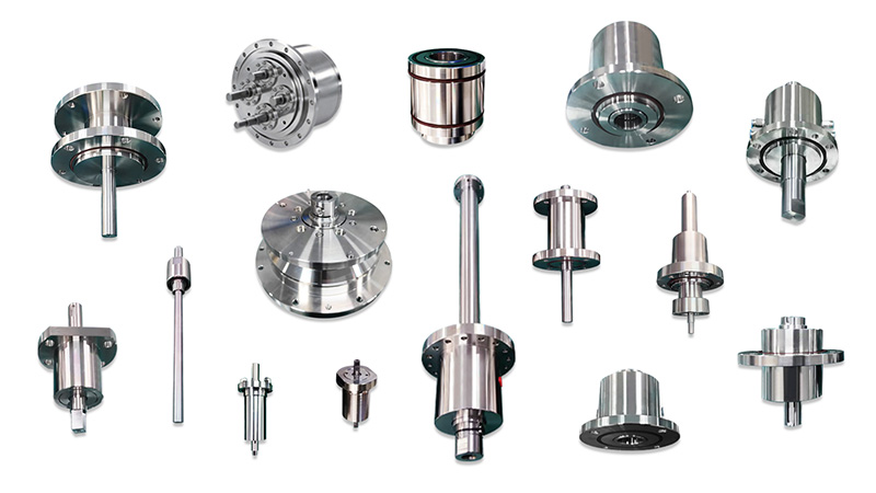
Hollow shaft (shaft-insert type) shaft diameter: standard range from 10mm to 50mm, non-standard customization available. Bearing configuration: standard (supported at both ends). Water cooling: water-cooled version available.
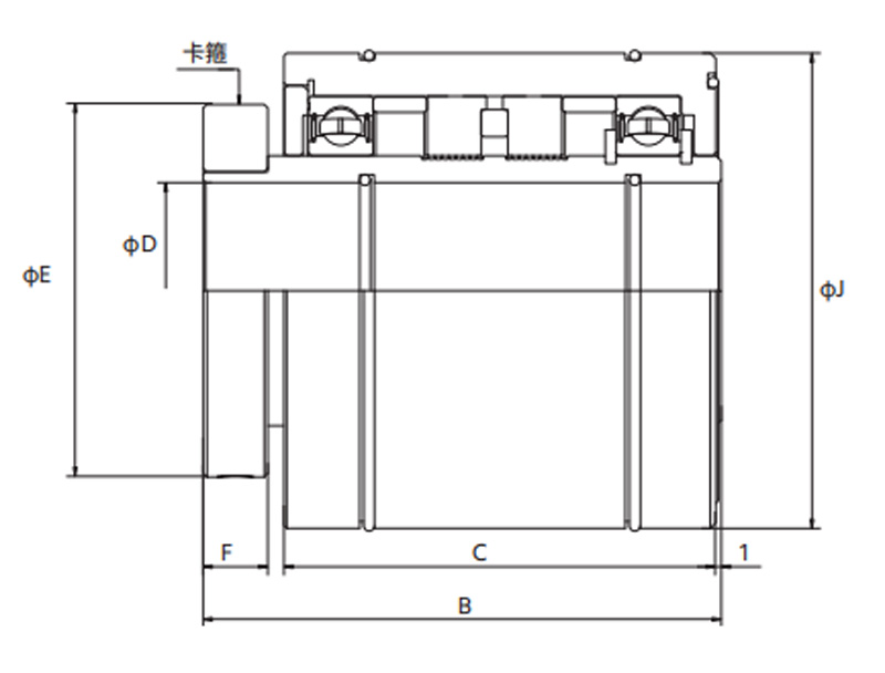
Specifications of KVF-type hollow shaft. Customers may use their own prepared shafts.
It offers design freedom. Specifications of bearings at both ends.
-
Precautions(*1): Solvents (acetone, alcohol, freon, oil, water, etc.) must not invade the ferrofluid sealing device.
(*2): Leak test shall be performed with a helium mass spectrometer leak detector.
(*3): Pressure exceeding the specified value shall not be applied. For vacuum applications, the applied pressure is 1kg/cm²; for pressurized applications, pressure shall only be applied up to the value specified in the technical specification.
(*4): When evacuating the vacuum chamber while the rotary shaft of the ferrofluid seal is stationary, or rotating it after a long stationary period in vacuum, the vacuum pressure will rise. This is an inherent characteristic of ferrofluid sealing devices and can be mitigated by measures such as pre-starting.
(*5): For water-cooled models, use room-temperature water with a flow rate of 1–3 L/min. Ordinary tap water is acceptable (chloride ion ≤200mg/L, iron content ≤0.3mg/L). In addition, condensation must be avoided, as condensation will cause bearing rust and result in poor rotation.
(*6): Please contact our technical sales staff when using the ferrofluid seal under the following conditions.
| KVF2010 | KVF2020 | KVF2025 | KVF2030 | KVF2040 | KVF2050 | KVF2075 | |
|---|---|---|---|---|---|---|---|
| B | 78 | 82.5 | 88 | 93 | 96 | 98 | 115 |
| C | 64 | 68.5 | 74 | 79 | 80 | 82 | 96 |
| ΦD | 10+0.03 +0.01 | 20+0.04 +0.02 | 25+0.04 +0.02 | 30+0.04 +0.02 | 40+0.04 +0.02 | 50+0.05 +0.02 | 75+0.06 +0.03 |
| ΦE | 34 | 44 | 49 | 54 | 69 | 79 | 109 |
| F | 10 | 10 | 10 | 10 | 12 | 12 | 15 |
| ΦG | 10-0.01 -0.03 | 20-0.01 -0.03 | 25-0.01 -0.03 | 30-0.01 -0.03 | 40-0.01 -0.03 | 50-0.01 -0.03 | 75-0.01 -0.03 |
| ΦJ | 48+0 -0.02 | 58+0 -0.03 | 63+0 -0.03 | 73+0 -0.03 | 88+0 -0.04 | 98+0 -0.04 | 137+0 -0.04 |
| Allowable Transmission Torque [kg.cm] | - | ||||||
| Vacuum Level [Torr] | 10-6(10-8) | ||||||
Allowable Helium Leak Rate [Pa.m³/sec(Torr.l/sec)] | <10-10/<10-9 | ||||||
| Pressure Resistance [kg/cm²] | 1.0 | ||||||
| Operating Temperature Range [℃] | 0~80 | ||||||
| Applicable Gas | Inert Gas | ||||||