
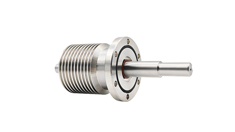
SVF Series
The ferrofluid adopts insert-type connection. Two O-rings on the outer diameter of the housing connect with the chamber bore to maintain static sealing. The ferrofluid shaft sleeve is rotatable. When the drive shaft is inserted into the shaft sleeve, two O-rings inside the sleeve compress the drive shaft to form a static seal between them. Rotation of the drive shaft drives the shaft sleeve to rotate together, solving the vacuum sealing problem of the drive shaft. It is suitable for vacuum sealing at low, medium and high rotational speeds under ambient temperature.
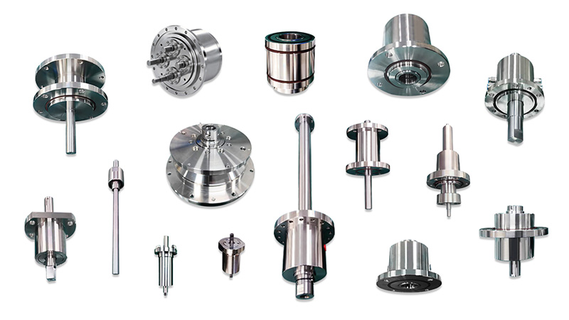
Solid shaft (shaft-equipped type) shaft diameter, bearing configuration: standard (supported at both ends). Water cooling: water cooling available upon request. Round straight type, flat cut
The most standard flange mounting type. Bearing design with bearings fitted at both ends.
Keyway machining on the shaft is an optional specification.
-
Precautions(*1): Solvents (acetone, alcohol, freon, oil, water, etc.) must not invade the ferrofluid sealing device.
(*2): Leak test shall be performed with a helium mass spectrometer leak detector.
(*3): Pressure exceeding the specified value shall not be applied. For vacuum applications, the applied pressure is 1kg/cm²; for pressurized applications, pressure shall only be applied up to the value specified in the technical specification.
(*4): When evacuating the vacuum chamber while the rotary shaft of the ferrofluid seal is stationary, or rotating it after a long stationary period in vacuum, the vacuum pressure will rise. This is an inherent phenomenon of ferrofluid sealing devices and can be mitigated by measures such as pre-starting.
(*5): For water-cooled products, use room-temperature water with a flow rate of 1–3 L/min. Ordinary tap water can be used (chloride ion ≤200mg/L, iron content ≤0.3mg/L). In addition, condensation must be avoided, as condensation will cause bearing rust and result in poor rotation.
(*6): Please contact our technical sales staff when using the ferrofluid seal under the following conditions.
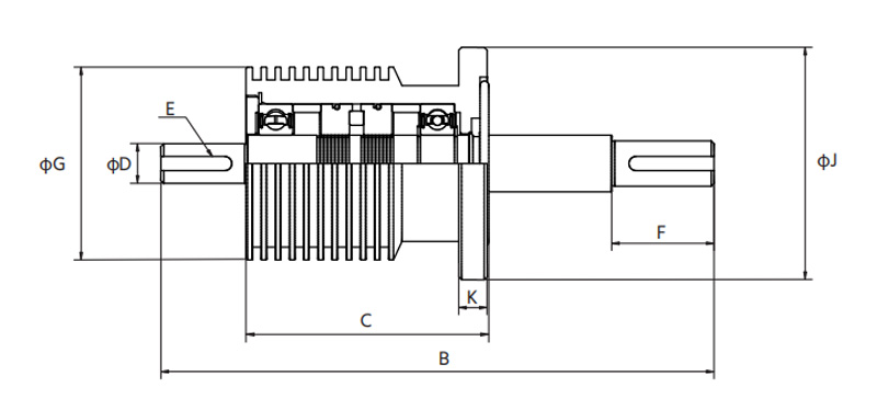
| SVF1006 | SVF1006 | SVF1012 | SVF1020 | |
|---|---|---|---|---|
| B | 97.5 | 119.5 | 133.5 | 151.5 |
| C | 57.5 | 69.5 | 73.5 | 81.5 |
| D | 6+0 -0.018 | 10+0 -0.022 | 12+0 -0.027 | 20+0 -0.033 |
| E | Depth 0.5D × Length 12Lg (Flat) | Width 3W × Depth 1.8D × Length 14Lg | Width 4W × Depth 2.5D × Length 20Lg | Width 6W × Depth 3.5D × Length 25Lg |
| F | 20 | 25 | 30 | 35 |
| G | 38 | 44 | 48 | 63 |
| J | 80 | 80 | 90 | 105 |
| K | 10 | 10 | 10 | 10 |
| Allowable Transmission Torque [kg.cm] | 9.7 | 6.2 | 124 | 615 |
| Vacuum Level [Torr] | 10-6(10-8)/10-5(10-7) | 10-6(10-8)/10-5(10-7) | 10-6(10-8)/10-5(10-7) | 10-6(10-8)/10-5(10-7) |
Allowable Helium Leak Rate [Pa.m³/sec(Torr.l/sec)] | <10-10/<10-9 | |||
| Pressure Resistance [kg/cm²] | 1.0 | |||
| Operating Temperature Range [℃] | 0~80 | |||
| Applicable Gas | Inert Gas / Reactive Gas | |||