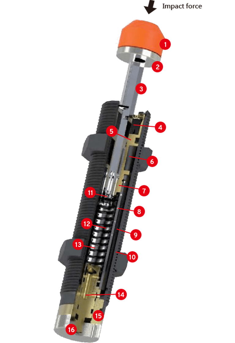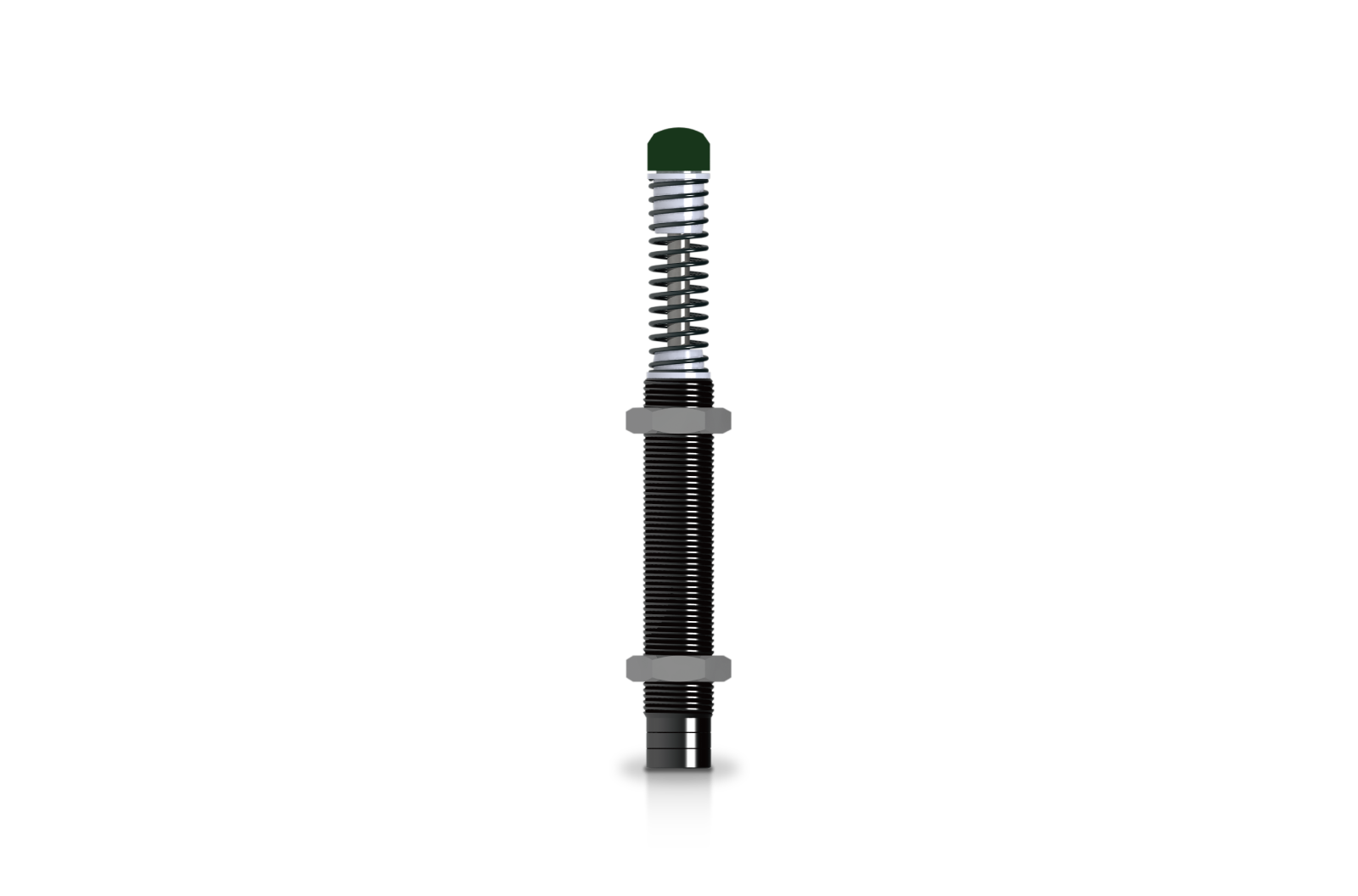
This chart is a typical shock absorber structure. When the impact head is stimulated by an external force, it will drive the piston rod to push the piston to squeeze the hydraulic oil in the inner tube. After the hydraulic oil is pressed, the specially designed oil drain will be applied from the inner tube. The holes flow out and also flow into the accumulator system. During the flow of the hydraulic fluid, the damper produces a curved damping effect that smoothly decelerates linearly until it stops. At this time, the external kinetic energy has been converted into the thermal energy of the buffer, and then the heat is dissipated into the air. Such a design can achieve energy circulation. When the external force disappears, the return spring returns the piston rod to the starting position, and it will wait for the next action. According to this principle, the shock absorber will be able to stop the moving object smoothly and effectively.